
Panasonic TNPA5330 SN board 7 or 6 blinks - detailed fault analysis and repair guide (TX-P42GT30, VT30, ST30)
I received a TX-P42GT30 with the famous 7 blink disease and it is the fifth Pana plasma with this defect. I am going to present my analysis of the causes of this defect, which appears after four to six years. On eBay I am seeing more of them these days.

The mounting hole backside under the microscope. We see blackened, burnt solder:


Dead driver transistor array and control chip (energy recovery H section)
Strangely, a driver transistor plus its control chip die, even though they are not responsible for any of the shorted power transistors. Q441 is still ok, yet those two are dead. I wonder why, but I have observed this twice already, only in 42 inch models though.

Broken IGBT (energy recovery L section)

The boards I have repaired also had a less obvious failure in Q451, a DG302 transistor. It has no dead short, but in diode test mode, it will leak between collector and gate and show a break-through voltage on the multimeter. It may not have this fault at the beginning and develop it once the other defects are repaired and you switch the device on for the first time! But don't worry, it will not destroy any other parts. It is best to routinely replace it.
See also below where I describe how to debug the recovery section.
The actual cause are loose screws. Why did they get loose? Because of the solder on the contacts. Solder is soft and flows under pressure. Why is this troublesome? Some screws and their contact pads conduct a lot of current into the metal panel chassis. When they become loose, the contact resistance increases and sparking occurs. This in turn leads to very high current peaks, which eventually kills (shorts) a diode. It is also possible that the increased resistance causes the mounting area to heat up and that kills a diode. This diode connects six transistors and another diode and those die immediately.
The next image shows the troubled screw position in close-up. It takes the full current from the DAF30 diode to the panel chassis ground. Other screws, which I'll show you below, pick up the current and from there it flows back to the power supply. Notice how the legs of the diode are discolored through heat! This one got enormously hot:
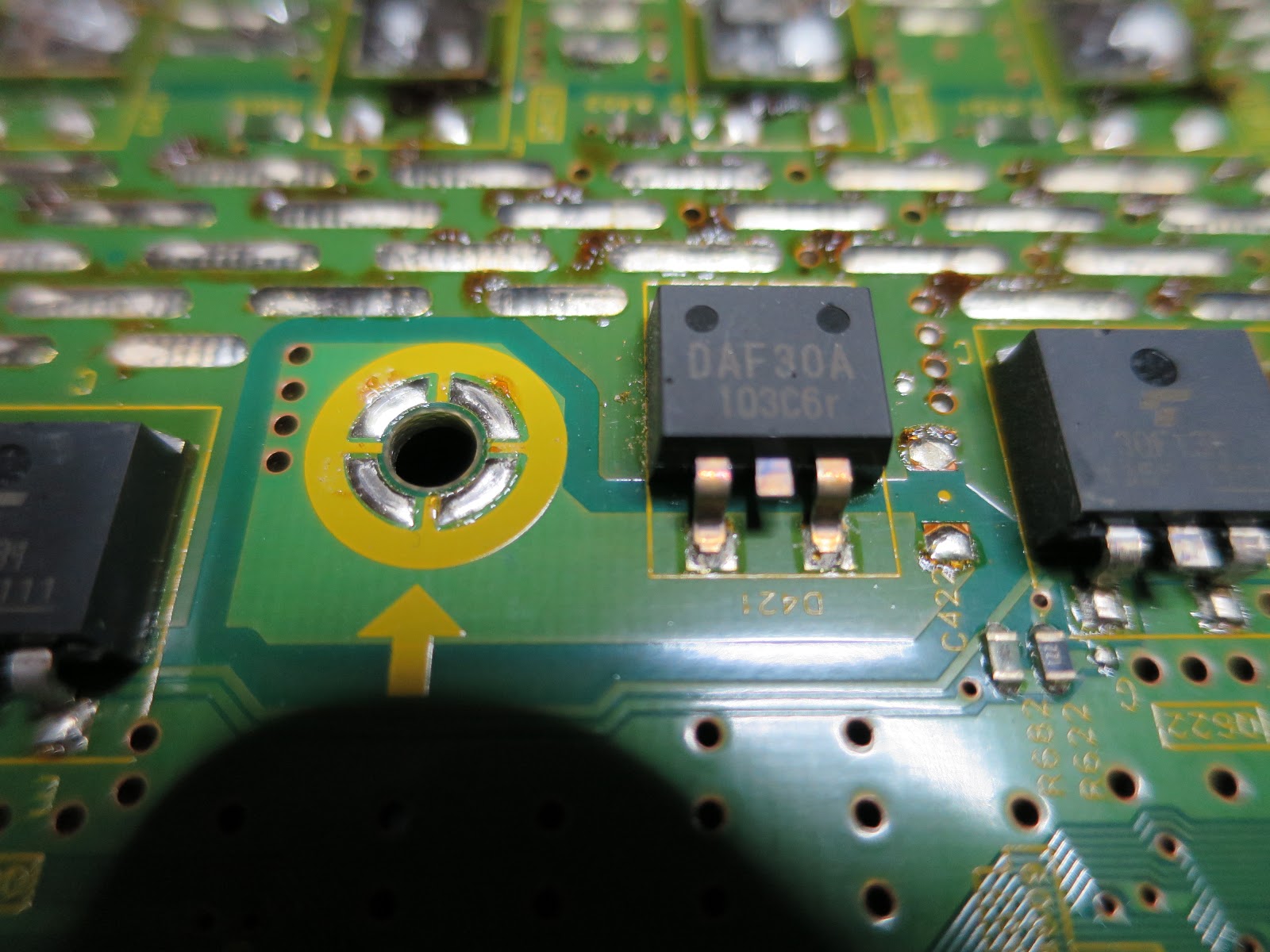
The mounting hole backside under the microscope. We see blackened, burnt solder:

And this is what a mounting point looks like:

As long as the screws stay under tension, the contact to the chassis will be good.
In the 60 series, Panasonic has learned from the screw disaster. This is an image from a 55STW60. No solder on the holes and screws with spring washers!

They also finally stopped using SMD power transistors and returned to decent heatsinks. Who needs silly super-flat TVs, anyway? I think those scan boards are built for eternity - maybe, provided the capacitors, which get all the heat from below, are holding up well.

In the next image, I marked the other screws, whose holes also had burn marks. The two on the top pick up the current from the chassis, which enters through the screw in the center. You see the already repaired board with my choice of transistors and diodes (see this post). Other screws have a proper bracket on the board or don't carry much current. There, the contacts looked ok.

And here is the section of the circuit where you can see all the affected high-power parts in one glance. The DAF30 diode is marked yellow. The diode and three transistors to the left and the three transistors to the right next to the troubled diode are all shorted when disaster strikes.

From 7 blinks to 6 blinks
6 blinks indicate a problem with the MIR voltage, the energy recovery voltage, which builds up across the blue C631. It must stay in a corridor around 120V.
Strangely, a driver transistor plus its control chip die, even though they are not responsible for any of the shorted power transistors. Q441 is still ok, yet those two are dead. I wonder why, but I have observed this twice already, only in 42 inch models though.

Broken IGBT (energy recovery L section)

The boards I have repaired also had a less obvious failure in Q451, a DG302 transistor. It has no dead short, but in diode test mode, it will leak between collector and gate and show a break-through voltage on the multimeter. It may not have this fault at the beginning and develop it once the other defects are repaired and you switch the device on for the first time! But don't worry, it will not destroy any other parts. It is best to routinely replace it.
See also below where I describe how to debug the recovery section.
How to repair this defect properly
- Replace all broken components
- Remove all solder on both sides of all screw mounting holes. Only apply a very thin and flat(!) layer of solder. It helps making a good contact.
- Clean the mounting points on the panel chassis from all black residue.
- For the screw next to the DAF30 diode and the two on the top, replace the original screws with ones with a spring washer. Make sure they are not too long, otherwise you will drill into the panel! The screws will not loosen much once the solder is gone, but for the critical ones I want extra safety.
Debugging the 6 blinks of the energy recovery circuit
Through my own stupidity I damaged an already repaired board and spent hours trying to find the reason for the 6 blinks. The device started, the green LED on the SN board briefly came on and then it immediately shut down. Not enough time to take measurements with a voltmeter. A not 100% working driver transistor was the culprit. Along the way I learned a lot about the circuit.
Get the manual for the TC-42GT30 from elektrotanya.com. This manual is top quality with zoom-able schematics. Page 69, chapter 12.27 SN1 Board Schematic Diagram. I have another for the TX-42 with pixelated graphics, where you can't read the part numbers.
The recovery voltage can be measured across C631. It should be around 120V. The protection activates below 36V and above 157V. The polarity is not important, just focus on the amount.
A multimeter in MIN-MAX mode may not be fast enough to catch the max amount. I used a digital storage oscilloscope in roll mode with 1ms time base. It showed the ramp-up of the voltage beautifully. However, this is not required, because if the protection circuit fires, there are only two possible cases, which a quick multimeter can detect in MIN-MAX mode:
If the voltage is missing, the recovery L section is not working. Most likely, Q451 has a problem as described above. Mine never had a full short. If it has, also replace Q552 and IC522.
If the amount is too high, the recovery H section is not working. Strangely, Q441 does not die, but its companions Q531 and IC502. This is a total mystery to me.
Spare parts
In THIS BLOG POST I talk about possible replacement for discontinued parts. I am trying my luck with the FGD4536 for all the power transistors, including the DG302.